Thin-wall Butt Weld Cap Distortion Control: Fit-up And Heat Input Rules
Welding distortion across thin-walled components stems from asymmetric circumferential shrinkage and intense heat concentration around the bevel. Controlling this deformation requires rigid internal backing fixtures, balanced skip welding, and precise heat input monitoring during root pass deposition.
Fit-Up Mechanics and Joint Preparation
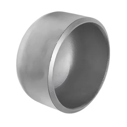
Large-diameter geometry exhibits low radial stiffness, making a standard butt weld cap prone to out-of-roundness before torch ignition. Misalignment along the joint circumference magnifies angular distortion, creating severe weld seam stresses when tack welds contract unevenly across thin cross-sections.
Clamping and Root Gap Uniformity
Fabricators maintain dimensional accuracy on a butt weld end cap through spider clamps and ceramic backing rings. These tools enforce circularity without inducing residual stress, ensuring equal root gap opening around the complete joint interface prior to filler metal deposition.
Welding Thermal Control Protocols
Distortion control on any butt weld pipe cap demands low heat input parameters combined with a balanced back-step sequence. Depositing short beads across diametrically opposed quadrants disperses thermal energy evenly, restricting expansion within the heat-affected zone effectively.
-
Symmetric quadrant tacking with bridge tacks anchors the joint circumference without penetrating the root face. This approach prevents localized contraction forces from pulling thin pipe walls inward before primary welding begins.
-
Deposition sequence follows diametrically opposed quadrants using short stringer beads. Spreading thermal energy across alternate sides minimizes asymmetric residual stress and stops localized angular shrinkage around the joint circumference.
Unstable generator current causes arc voltage fluctuations, disrupting heat input control during mechanized passes. While field offices protect sensitive tools through a home stabilizer 7kva, welding machines require dedicated industrial line conditioners to prevent erratic thermal spikes.
Joint Fit-Up and Welding Parameters
| Inspection Metric | Target Specification | Corrective Action |
|---|---|---|
| Root Gap Width | 2.0 mm to 3.0 mm | Adjust spacer wedges |
| Bevel Angle Range | 30° to 37.5° | Mechanical edge milling |
| Radial Offset | Under 1.5 mm | Adjust internal spider clamp |
| Interpass Temperature | Under 150°C | Forced dry airflow pause |
Ovality Verification Sequence
-
Measure outer diameter along four perpendicular axes using calibrated vernier calipers. This step records initial radial variations across the circumferential seam before subsequent hydrostatic testing occurs.
-
Calculate maximum ovality deviations against specified project design tolerances. Any recorded diameter divergence exceeding allowable code limits requires mechanical jacking fixtures combined with controlled stress relief.
Strict adherence to symmetrical joint fitting and controlled amperage keeps thin wall components true to specified roundness. Eliminating excessive heat concentration preserves structural geometry, guaranteeing pipeline integrity without costly field rework.