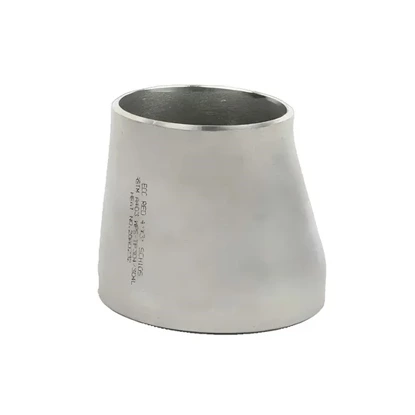
Butt Weld Reducer Drawing Die Calculation: Inner Datum Punch & Cavity Clearances
Forming a precise butt weld reducer requires exact tooling geometries. When fluid dynamics demand strict internal diameters, engineers establish the inner pipe surface as the primary calculation datum. This approach dictates every subsequent punch and cavity dimension.
Inner Surface Datum Fundamentals in Deep Drawing
Selecting the inner surface as a baseline eliminates flow restriction issues in high-pressure pipelines. During deep drawing, metal undergoes radial compression and circumferential plastic deformation. Tooling designers calculate the punch diameter directly from the required inner specification.
A steel pipe reducer experiences uneven wall thickening during cold forming. As the blank draws inward, compressive hoop stresses increase material thickness near the small end. Clearances between the punch and cavity must accommodate this natural material growth.
Core Equations for Punch and Cavity Sizing
For an inner-datum butt weld reducer, the punch controls the internal profile, while the die cavity accounts for wall thickness and clearance. Under ASME B16.9 tolerances, equations incorporate manufacturing allowances and material elasticity to prevent galling.
-
Establish the nominal inner diameter of the finished fitting at both the large and small ends.
-
Subtract the material elastic recovery value to determine the final outer working diameter of the punch.
-
Calculate the maximum thickening ratio at the reduced neck using the initial blank thickness and drawing coefficient.
-
Add twice the single-side die clearance and the thickened wall value to the punch diameter to get the cavity dimension.
Punch Working Dimension Formula
To size the punch for a concentric reducer fitting, engineers apply the equation:
Dp = (Dmin + k ⋅ Δ) − δp
Here, Dp represents punch diameter, Dmin is minimum inner diameter, k is the datum factor, Δ is dimensional tolerance, and δp is machining allowance.
Die Cavity Dimension Formula
The cavity controls the outer compression zone. For a smooth conical reducer profile, the cavity diameter (Dd) equals the punch diameter plus twice the single-side clearance (Z):
Dd = Dp + 2Z
This prevents surface scoring during high-tonnage press strokes.
Determining Optimal Single-Side Die Clearance
Single-side die clearance (Z) directly governs outer surface finish, drawing tonnage, and tooling lifespan. When referencing the inner surface of a butt weld reducer, the clearance equals the maximum thickened wall gauge plus a material-specific gap coefficient (c):
Z = tmax + c ⋅ t0
-
Carbon Steel Alloys: Gap coefficients range from 0.05 to 0.08 times initial blank thickness (t0), accommodating moderate work hardening during cold reduction.
-
Austenitic Stainless Steels: Coefficients increase to 0.08 through 0.12 to counter severe work hardening and prevent adhesive wear against the cavity walls.
-
Sanitary Thin-Wall Tubes: Precision components like a 2 to 1.5 tri clamp reducer utilize minimal clearances (0.02 to 0.04) to achieve mirror-like internal finishes without secondary machining.
Standard Clearances and Allowances for Pipe Reducers
The following table outlines standard calculation parameters for inner-datum deep drawing tooling across common industrial wall schedules:
| Material Grade | Initial Blank Thickness (t0) | Thickening Factor (m) | Gap Coefficient (c) | Single-Side Clearance (Z) | Punch Machining Allowance (δp) |
|---|---|---|---|---|---|
| ASTM A234 WPB | 6.00 mm | 1.12 | 0.06 | 7.08 mm | 0.020 mm |
| ASTM A403 WP304 | 4.50 mm | 1.15 | 0.09 | 5.58 mm | 0.015 mm |
| ASTM A403 WP316L | 3.00 mm | 1.16 | 0.10 | 3.78 mm | 0.012 mm |
| Alloy Steel P11 | 8.00 mm | 1.10 | 0.07 | 9.36 mm | 0.025 mm |
Compensating for Springback and Wall Thickening
Cold forming induces residual stresses that cause elastic springback once the punch retracts. Engineers modify the punch cone angle by 0.5 to 1.5 degrees inward. This over-bending ensures the butt weld reducer relaxes into exact geometric alignment.
Anisotropy in rolled sheet metal creates uneven rim movement during compression. Tooling specialists run finite element simulations to map localized thickening across the transition zone. Modifying the cavity entry radius distributes contact pressure evenly, stopping premature die fatigue.